Posted on 8 Comments

How to install NUTTYFI Wifi IoT Board in Arduino IDE

In this tutorial, you’ll learn how to install the NuttyFi boards package in the Arduino IDE using our official Board Manager URL.

If you don’t have the Arduino IDE yet, download it from the official site: https://www.arduino.cc/en/Main/Software.

Board Manager URL (copy this)

https://raw.githubusercontent.com/itsbhupendrasingh/Nuttyfi/main/package/package_nuttyfi_index.json


Tip: Arduino IDE supports multiple Additional URLs. Put each on a new line (IDE 2.x) or separate with commas (IDE 1.8.x).


If you want to install NuttyFi32 Board in your Arduino IDE, then just follow our another tutorial guide on How to install ESP32 Board in Arduino IDE.

Step-by-Step (Arduino IDE 2.x and 1.8.x):

Step 1: Open Arduino IDE (2.x recommended).

Step 2: Open Preferences

  • Windows/Linux: File → Preferences
  • macOS: Arduino IDE → Settings/Preferences

Step 3: Add the NuttyFi JSON URL in Additional Boards Manager URLs (paste the URL above), then OK/Save.

https://raw.githubusercontent.com/itsbhupendrasingh/Nuttyfi/main/package/package_nuttyfi_index.json

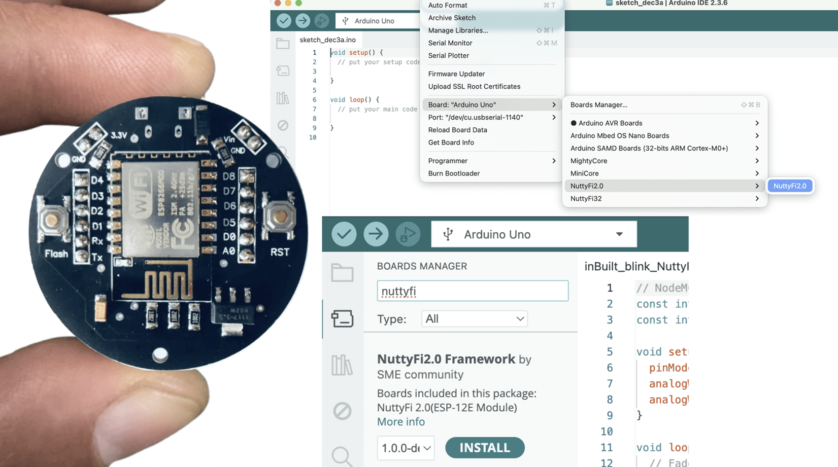
Step 4: Open Boards Manager → Tools → Board → Boards Manager…

Step 5: Search “NuttyFi” → select the NuttyFi package (publisher: SME Dehradun / Schematics Microelectronics) → Install.

Step 6: Select your board → Tools → Board → NuttyFi Framework → NuttyFi 2.0.

Step 7: Select the PortTools → Port (choose the new COM/tty) like shown in below image. 

And That’s it. Your NuttyFi board is ready to code.  Click Verify then Upload. The onboard LED should blink.

Quick Test (Blink with inbuilt LED)

Test Sketch (Blink)

// Minimal Blink for NuttyFi inbuilt Led

#ifndef LED_BUILTIN
#define LED_BUILTIN D4 // LED is on GPIO2
#endif

void setup(){
  pinMode(LED_BUILTIN, OUTPUT);
}

void loop(){
  digitalWrite(LED_BUILTIN, !digitalRead(LED_BUILTIN));
  delay(500);
}
  

Quick Test (Fade with inbuilt LED)

LED Fade (NuttyFi IoT Board)

// NuttyFi IoT Board onboard LED (GPIO2 / D4), active-LOW
const int LED_PIN = D4;     // or use LED_BUILTIN
const int PWM_MAX = 1023;   // ESP8266 analogWrite range (0..1023)

void setup() {
  pinMode(LED_PIN, OUTPUT);
  analogWriteRange(PWM_MAX);
  analogWriteFreq(1000);    // 1 kHz (optional)
}

void loop() {
  // Fade IN (dim -> bright)
  for (int b = 0; b <= PWM_MAX; b += 5) {
    analogWrite(LED_PIN, PWM_MAX - b); // invert for active-LOW
    delay(5);
  }
  // Fade OUT (bright -> dim)
  for (int b = PWM_MAX; b >= 0; b -= 5) {
    analogWrite(LED_PIN, PWM_MAX - b); // invert for active-LOW
    delay(5);
  }
}
  

Happy Coding. 

8 thoughts on “How to install NUTTYFI Wifi IoT Board in Arduino IDE

  1. […] How to install wifi board ESPxx series to Arduino IDE. https://www.nuttyengineer.com/nuttyfi-iot-board-in-arduino-ide/ […]

  2. […] If you don’t have a wifi board installed in your arduino IDE, then this the link to show you, how you can install NuttyFi/ NodeMCU Wifi to the arduino IDE. […]

  3. […] You don’t know how to install NUTTYFI board in Arduino Ide, visit to our post How to install NUTTYFI IoT Board in Arduino ide. […]

  4. Hi,
    You need to watch our video on the Blynk2 errors. https://youtu.be/EPhY_hDozeo
    follow all the instruction and it will resolve your problem.

Leave a Reply

This site uses Akismet to reduce spam. Learn how your comment data is processed.