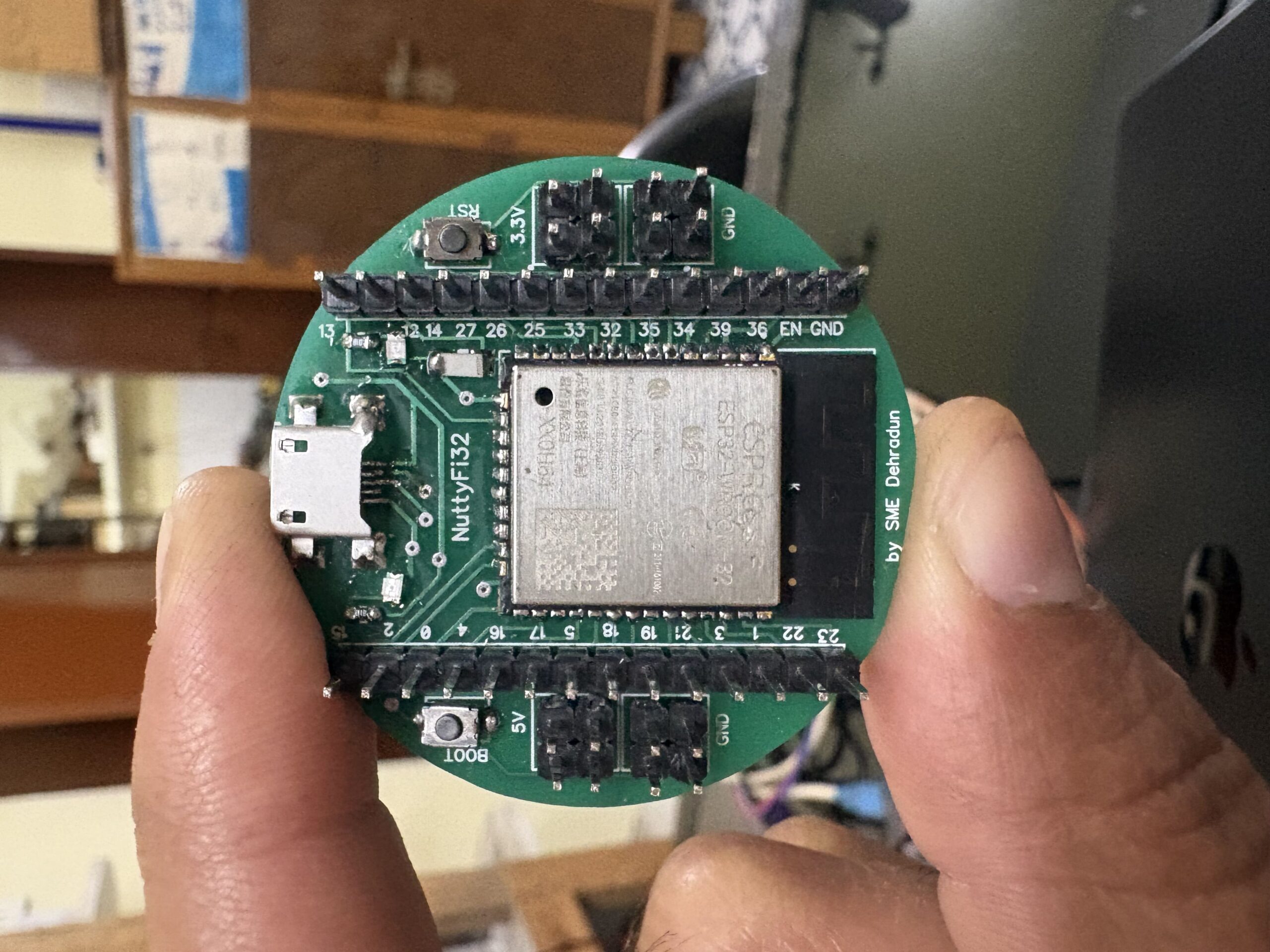
The NuttyFi2.0 development board has its own dedicated Arduino Board Manager package. This means you can install board support directly using a custom Board Manager JSON — no need to manually pick a generic ESP32 board.
Unlike the official ESP32 package (which installs many ESP32 board definitions and increases storage usage), NuttyFi2.0 uses an independent board package, designed exclusively for NuttyFi2.0 hardware. This keeps installation lightweight, fast, and easy to manage, without unnecessary boards. It’s perfect for developers who prefer a clean, minimal, and focused development setup.
Below are step-by-step instructions to install and start using NuttyFi2.0 in Arduino IDE.
🛠 Step 1: Install Arduino IDE
Download and install the latest Arduino IDE from:
https://www.arduino.cc/en/softwareLaunch the Arduino IDE after installation.
🔗 Step 2: Add NuttyFi2.0 Board Manager URL
In Arduino IDE go to:Go to:
Windows / Linux:
File → PreferencesmacOS:
Arduino IDE → Settings / Preferences
- In Additional Boards Manager URLs, paste the following NuttyFi2.0 Board Manager link.
File → Preferences
https://raw.githubusercontent.com/itsbhupendrasingh/Nuttyfi/main/package/package_nuttyfi_index.json
- Click OK.
Note: If you already have one or more URLs there, separate each with a comma.
If you want to install NuttyFi32 Board in your Arduino IDE, then just follow our another tutorial guide on How to install NuttyFi32 Board in Arduino IDE.

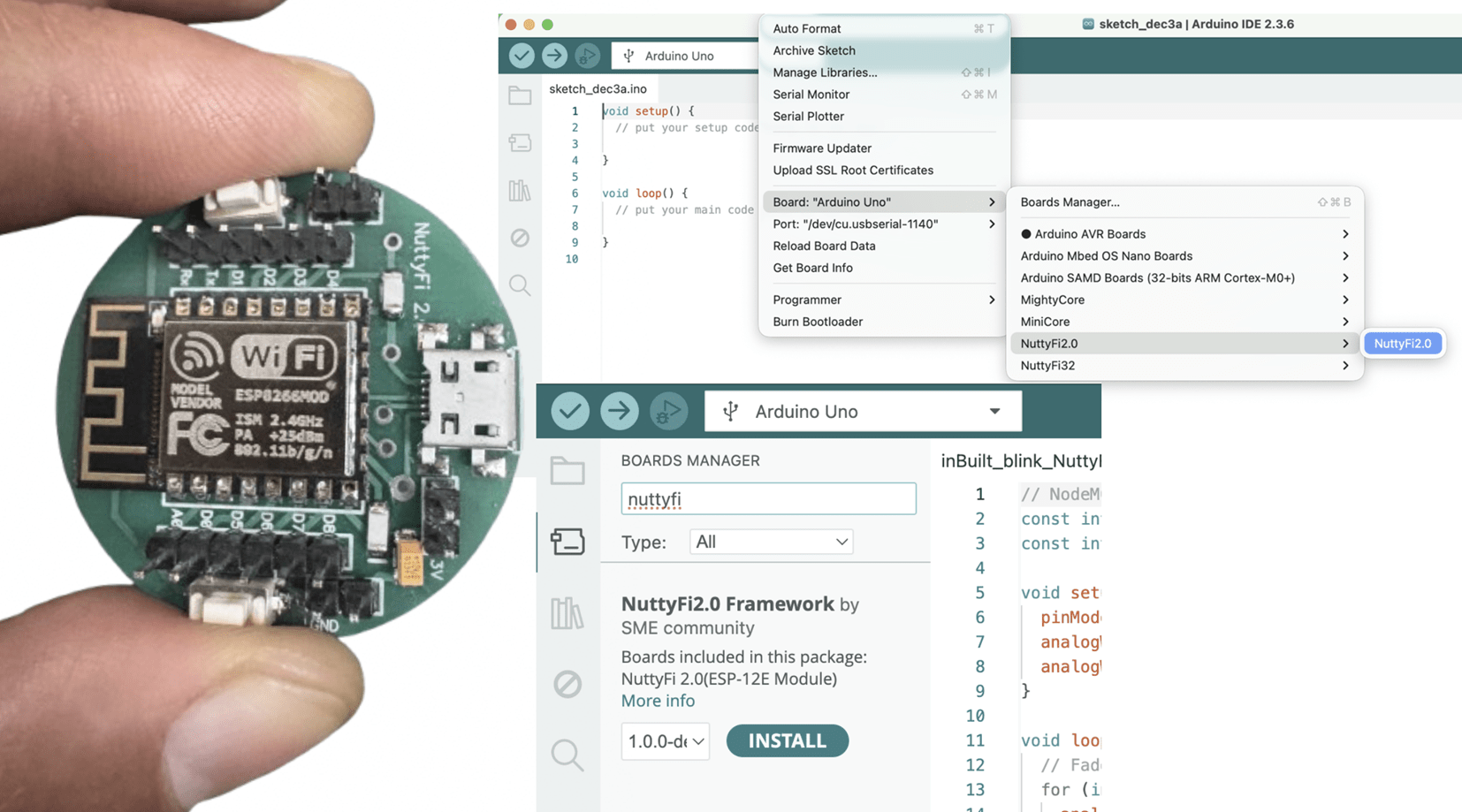
📥 Step 3: Install NuttyFi2.0 Board Package
Go to:
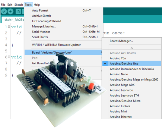
Tools → Board → Boards Manager
Step 4: Open Boards Manager → Tools → Board → Boards Manager…

In the search bar type:
NuttyFi2.0

When the board package appears, click → Install.
Wait for installation to finish.
🧠 Step 4: Select NuttyFi2.0 Board
Go to:
Tools → BoardScroll down and select:
NuttyFi2.0

💡 This loads NuttyFi2.0-specific settings (flash size, CPU, partition scheme).
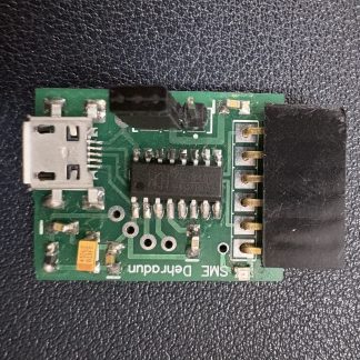
🖥 Step 5: Connect Your Board and Select COM Port
Connect NuttyFi2.0 to your computer using a USB cable.
Go to:
Tools → PortSelect the appropriate port:
Windows: COMx (e.g., COM4)
macOS/Linux: /dev/ttyUSBx or /dev/ttyACMx

⚠️ Note: The COM port shown in examples may differ on your computer. Always select the one that appears when NuttyFi2.0 is connected.
🧑💻 Step 6: USB Driver Installation (If Needed)
If your computer does not detect the board, you may need drivers depending on the USB-to-UART chip used:
Note: Still the NuttyFi2.0 board does not appear in the COM port list or you face USB driver issues, please watch this troubleshooting video below:
🧪 Step 8: Upload a Test Sketch
Let’s verify the NuttyFi2.0 board by running a simple test program.
✅ Led Blink Test Sketch (inbuilt).
Copy the code below and paste it into the Arduino IDE. Upload the sketch to the NuttyFi2.0 board.
After successful upload, the on-board LED will blink at an interval of 500 ms (half a second), confirming that the board is working correctly.
// Minimal Blink for NuttyFi2.0 inbuilt Led

#ifndef LED_BUILTIN
#define LED_BUILTIN D4 // LED is on GPIO2
#endif

void setup(){
  pinMode(LED_BUILTIN, OUTPUT);
}

void loop(){
  digitalWrite(LED_BUILTIN, !digitalRead(LED_BUILTIN));
  delay(500);
}
✅ LED Fade Test Sketch (inbuilt)
This example demonstrates PWM-based LED fading on the NuttyFi2.0 board.
Copy the code below and paste it into the Arduino IDE, then upload the sketch to the NuttyFi2.0 board.
After a successful upload, the on-board LED will gradually fade in and fade out, verifying PWM functionality and confirming that the board is operating correctly.
// NuttyFi2.0 IoT Board onboard LED (GPIO2 / D4), active-LOW
const int LED_PIN = D4;     // or use LED_BUILTIN
const int PWM_MAX = 1023;   // Nuttyfi2.0 analogWrite range (0..1023)

void setup() {
  pinMode(LED_PIN, OUTPUT);
  analogWriteRange(PWM_MAX);
  analogWriteFreq(1000);    // 1 kHz (optional)
}

void loop() {
  // Fade IN (dim -> bright)
  for (int b = 0; b <= PWM_MAX; b += 5) {
    analogWrite(LED_PIN, PWM_MAX - b); // invert for active-LOW
    delay(5);
  }
  // Fade OUT (bright -> dim)
  for (int b = PWM_MAX; b >= 0; b -= 5) {
    analogWrite(LED_PIN, PWM_MAX - b); // invert for active-LOW
    delay(5);
  }
}
⭐ NuttyFi2.0 Resources
For source code, board packages, updates, and documentation, visit the official NuttyFi GitHub repository: