NuttyFi32 RoadTest Program
The NuttyFi32 RoadTest program invites engineers and developers to independently evaluate the NuttyFi32 WiFi IoT board in real-world conditions. Participants will receive hardware and are expected to test, document, and share practical feedback with the community.

What is a RoadTest?
Category: ESP32 Development Board
Manufacturer: SME Dehradun
RoadTest Status: 🟢 Applications Open
RoadTest Duration: 4 Weeks
Units Available: 5
Who Can Participate?
This RoadTest enables selected engineers to evaluate the NuttyFi32 development board in real-world conditions and publish experience-based technical feedback.
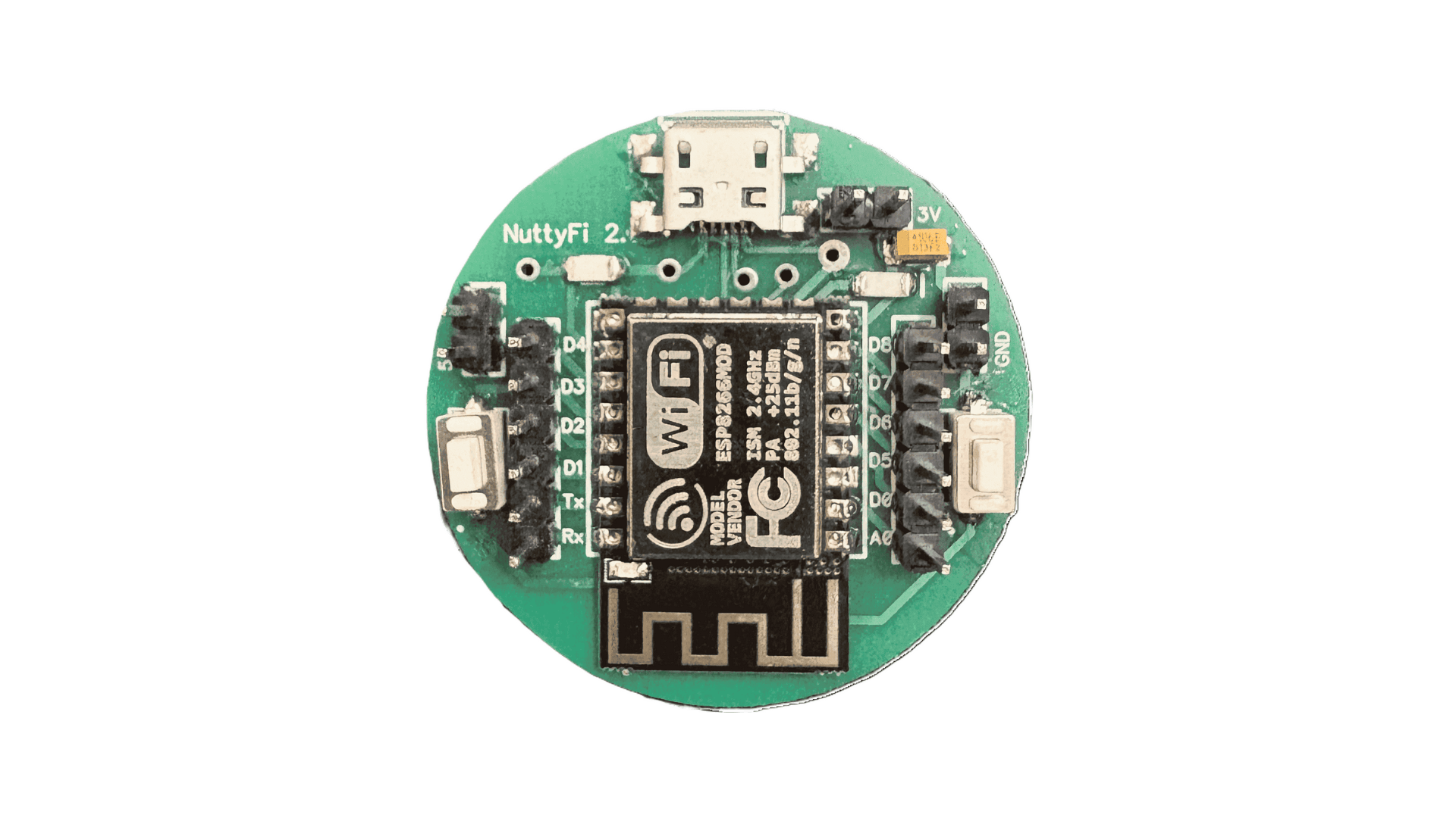
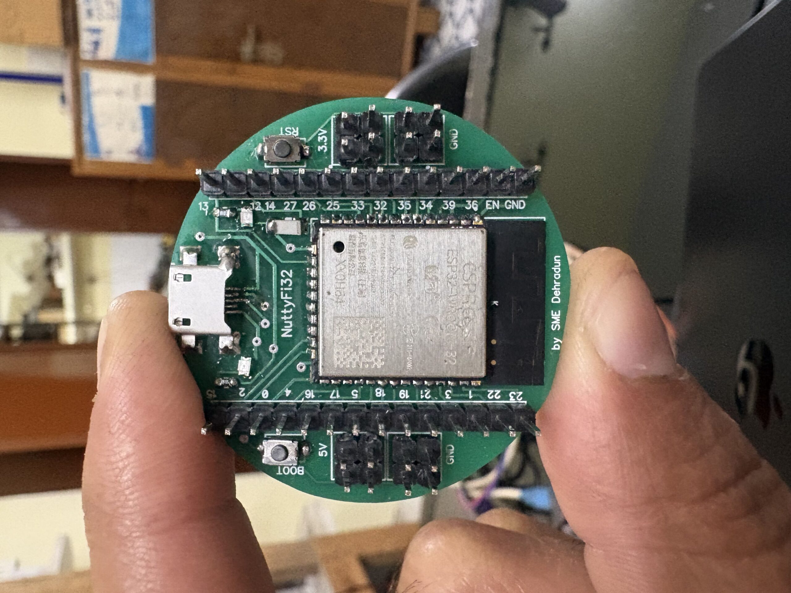
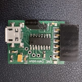
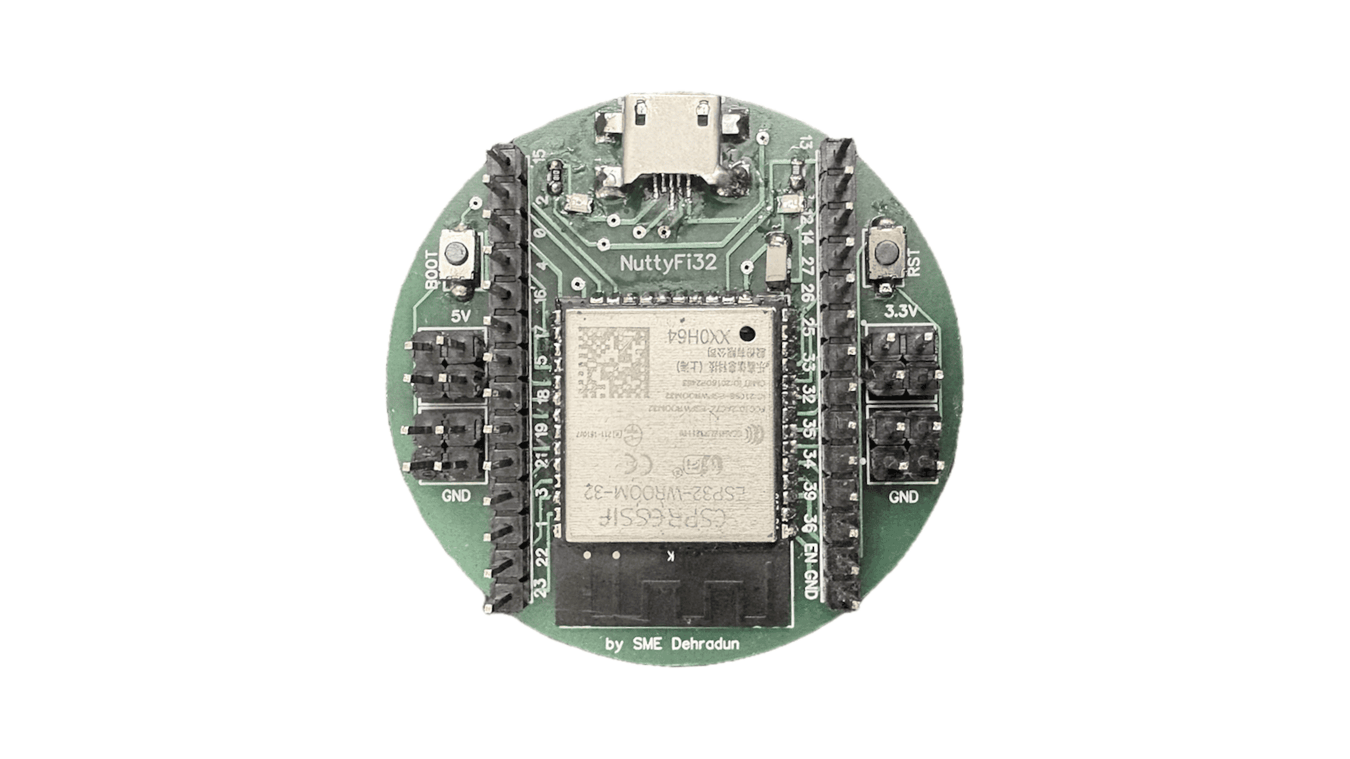
Product Overview
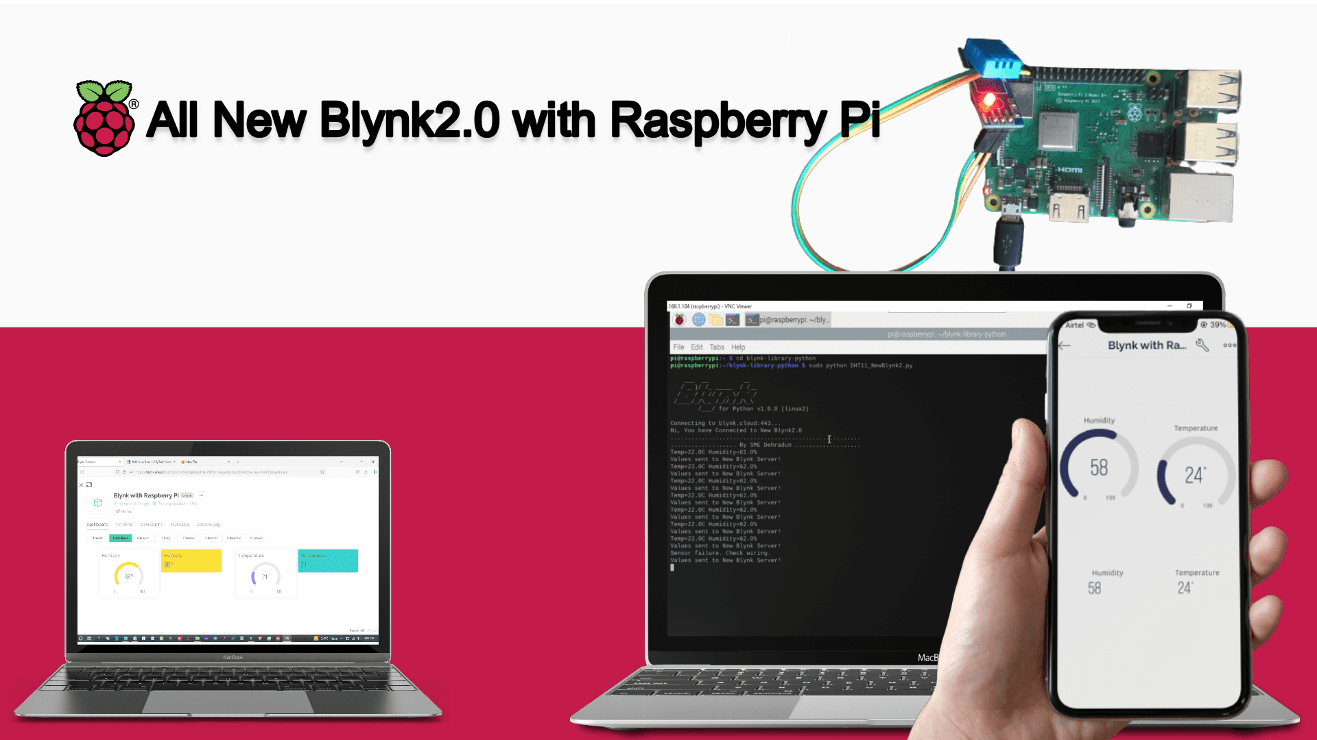
✅ The NuttyFi32 is a developer-focused ESP32-based board designed for Wi-Fi connectivity testing, OTA workflows, and embedded firmware validation.
✅ The RoadTest focuses on evaluating the board beyond bench testing, including real usage scenarios, stability, and developer experience.
What We Want to Lear
Participants are encouraged to evaluate the product in real projects and provide feedback on:
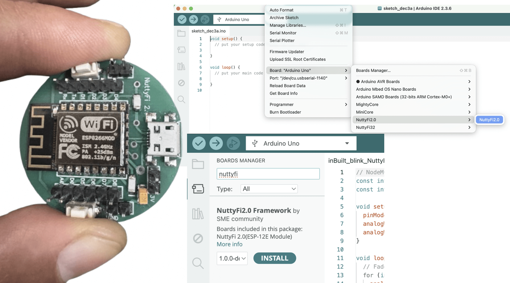
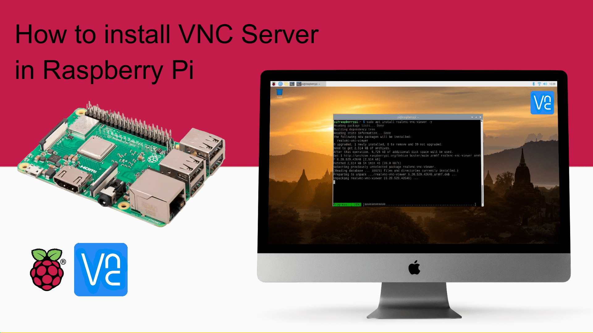
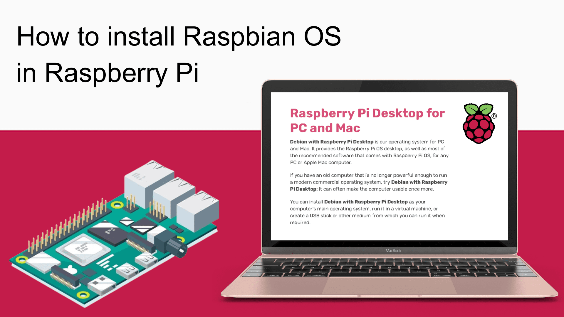
Setup and first-use experience
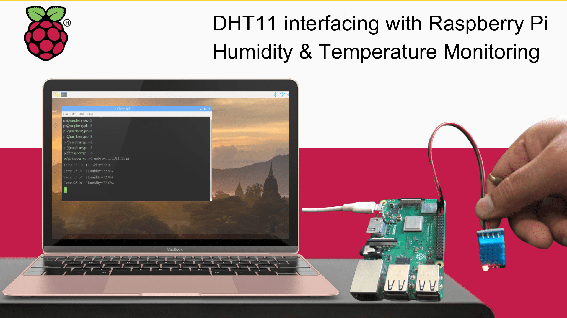
Wi-Fi connectivity and stability
Firmware flashing and OTA behavior
Reliability during continuous operation
Power behavior and reset handling
Overall developer usability
Limitations and improvement areas
Eligibility Criteria
This RoadTest is intended for:
Electronics or embedded engineers
IoT developers and system integrators
Makers with real project experience
Students with hands-on embedded background
Applicants should have:
Prior experience with ESP32 / embedded systems
A clear idea of how they plan to use the board
Willingness to document and publish feedback
RoadTest Process
✅ Step 1 — Apply
Interested participants submit an application describing their background and intended use case.
✅ Step 2 — Selection
Selected testers are announced after application closure. Devices are shipped to selected participants.
✅ Step 3 — Test & Document
Testers use the product in real projects during the RoadTest period and share periodic updates.
✅ Step 4 — Publish Review
Each tester publishes a final, structured review covering their experience, findings, and recommendations.
What We Want to Learn
Tester Responsibilities
Selected RoadTesters are expected to:
Use the product in a real project or application
Share at least one mid-RoadTest update
Publish a detailed final review
Highlight both positives and limitations
Provide honest, unbiased feedback
There is no requirement for positive reviews.
Suggested Review Structure
Testers should cover:
Introduction & expectations
Unboxing & first impressions
Setup and configuration experience
Project or use case description
Performance and reliability observations
Issues or limitations encountered
Suggestions for improvement
Final verdict
Photos, logs, and measurements are encouraged where applicable.
Program Guidelines
Tester Responsibilities
RoadTest units are provided free of cost
Testers keep the hardware after completion
Reviews must be original and honest
Failure to submit a review may affect eligibility for future RoadTests
NuttyEngineer may feature submitted content with proper credit
Apply to This RoadTest
✅ Applications are open for a limited time.
✅ Interested participants should apply using the form below.