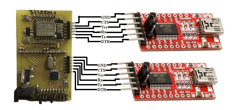
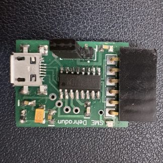
We have Customized boards that are Compatible with Arduino IDE that use the FT232RL. If you have one of these older versions, you’ll want to use the FDTI drivers as well. if you are using CH340 based programmer then you can buy it from here
Now that you know why the FTDI Basic is important and what products it is used for, let’s learn how to install the drivers.
Windows – Quick and Easy
Note: The tutorial is compiled with windows 7. The process should be very similar for other versions of Windows. For most late versions of windows, such as 8.1 through Windows 10, the hardware may work fine without any driver install. If you can’t locate a COM port for your hardware, then the set of instructions below is the possible fix.
Note for Educators: You will most likely need to obtain administrative privileges from your network or IT administrator in order to install these drivers.
By default, windows does not have FTDI drivers installed. If you plug in your FTDI, open the Arduino IDE, go to ‘Tools -> Serial Ports’, and see nothing, you need the drivers! Let’s go get them!
Download a copy of the v2.12.28 FTDI VCP Driver Executable here:
WINDOWS FTDI VCP DRIVER EXECUTABLE – V2.12.28 (CDM21228_SETUP.EXE)
Otherwise, visit FTDI’s VCP official Drivers page for the latest download of the Windows. if you are using CH340 ic based programmer, then download it from here at CH340 Driver’s official page. FTDI Driver executable and clicking on the Window’s “Available as a setup executable” link. Make sure to unzip the executable before proceeding to the next step.
Choose ‘Run’ once it is has finished downloading, or find the file you just downloaded “CDM21228_Setup.exe” and double-click it to run it.
Note: At the time of this tutorial, the images were referencing the old “v2.12.00” FTDI VCP driver executable. The installation process will be the same regardless of the version number.
Choose ‘Extract’ and continue through the installation until it finishes.
If everything was successful, you should see some nice green check marks, indicating success!
Note: You may need administrator privileges on your machine in order for this to run properly. If things didn’t work out, try the next section of this tutorial: Windows – In Depth.
Open up the Arduino IDE, and go to ‘Tools -> Serial Port’. If you now have a COM port, congratulations! Again, if something went wrong, either retry this tutorial or give Windows – In Depth a try!
Windows – In Depth
Note: The screen shots in this tutorial are from Windows 7. The process should be very similar for other versions of Windows. The exception to this is Windows 8. For instructions on how to disable device driver signatures, please visit this tutorial.
Note for Educators: You will most likely need to obtain administrative privileges from your network or IT administrator in order to install these drivers.
Plug in your FTDI using a USB cable. Windows doesn’t have the correct drivers, so let’s find them!
Navigate to the FTDI website, and choose the ‘VCP’ (Virtual Com Port) option near the bottom.
Now choose either the 32 bit version or the 64 bit version. Not sure which you have? The next steps will go over how to find that information. If you already know which version you are running, you may skip the next two steps.
Open the start menu, right-click on ‘Computer,’ and left-click on ‘Properties’.
Look under ‘System type,’ to see which version you have.
Now go back to the FTDI site, right-click on the correct version, and save it to your computer. Remember where the files are saved. We’ll need them in the next step.
Navigate to the folder containing the files. They will be inside of a .zip file, so you’ll need to extract them. Right-Click on the .zip file, and choose ‘Extract All…’ When the next window appears, as shown above, pay attention to where it is extracting the files. Make sure that ‘Show extracted files when complete’ is checked, and click ‘Extract’.
When the extraction is complete, the folder is opened. Again, take note of this folder location. This is the one containing the drivers.
We’re almost there! Open the start menu, right-click on ‘Computer’, and left-click on ‘Manage’. You will need administrator rights to do this. If you aren’t an administrator on your computer, talk to the person who is and have them enter their credentials.
Left-click on ‘Device Manager’ in the leftmost column. Here is where we see the offending hardware. It has an exclamation mark next to it.
Right-click on ‘FT232R USB UART,’ and left-click ‘Update Driver Software…’
Now choose ‘Browse my computer for driver software’.
Left-click ‘Browse,’ and navigate to the location of the extracted files. Choose the extracted folder. There is no need to search any further in the folder. Then left-click ‘OK’.
Make sure ‘Include subfolders’ is checked (very important!), and left-click ‘Next’.
After a moment, you will see a success message! Left-click ‘Close’.
The Device Manager page will refresh and you will see a new item with an exclamation mark named ‘USB Serial Port’. You will need to install a second driver for the same device. Follow the steps 1-15, as before, and use the same driver folder too!
Once those steps are complete, you will see another success message! Left-click ‘Close’.
The Device Manager Page will refresh again and show ‘USB Serial Port (COMxx),’ where xx = some number. Congratulations, you now have the proper FTDI drivers and can begin to use your device!
Open up the Arduino IDE, and go to ‘Tools -> Serial Port’. If you now have a COM port, congratulations! Again, if something went wrong, either retry this tutorial or give Windows – In Depth a try!
Note: You should only need to go through this process once. Every subsequent FTDI device you plug in should now have these drivers associated with it. However, if this is not the case, you can follow these instructions again for other devices.
Note: If you have more than one FTDI device plugged in to your computer at the same time, all of the devices will show up in the Arduino IDE’s Serial Port menu and device manager. To figure out which device is which, look under the Arduino IDE’s ‘Serial Port’ menu. Take note of the names of each device. Then unplug the device you want to use. Go back to the ‘Serial Port’ menu. The device you unplugged should no longer be listed. That is the device you want. Plug it back in, and select the device that has now reappeared.
You can determine what COM port an FTDI device enumerated to by opening the device manager and browsing the “Ports (COM & LPT)” tree.
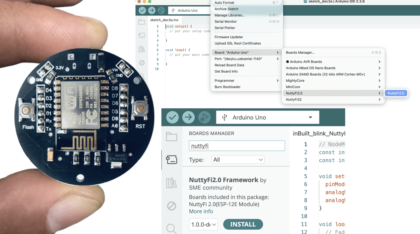
After that Connect NUTTYFI to your Computer using FTDI USB to UART Bridge & got to tools -> boards-> NodeMCU 1.0(ESP-12E Module & Select the Port like COM3.
after that copy these code (codes given below) to your arduino IDE & compile & upload to NUTTYFI & all done.
/**************************************NUTTYFI****************************/
// connect LED Positive pin at D6 of NUTTYFI. Connect Negative pin of LED to GND at NUTTYFI.
const int led = D6;
void setup() {
pinMode(led, OUTPUT); // initialize digital pin 'led' as an output.
}
// the loop function runs over and over again forever
void loop() {
digitalWrite(led, HIGH); // turn the LED on (HIGH is the voltage level)
delay(1000); // wait for a second
digitalWrite(led, LOW); // turn the LED off by making the voltage LOW
delay(1000); // wait for a second
}
/*********************************************************/
/**************************************NUTTYFI****************************/
// include the library code:
#include <LiquidCrystal.h>

// initialize the library with the numbers of the interface pins
LiquidCrystal lcd(D2, D3, D4, D5, D6, D7);

void setup() {
// set up the LCD's number of columns and rows:
lcd.begin(16, 2);
// Set the cursor
lcd.setCursor(0, 0);
// Print a message to the LCD.
lcd.print("Hi! Welcome");
}

void loop() {

lcd.setCursor(0, 1);
lcd.print("to NUTTYFI");
lcd.setCursor(12, 1);
lcd.print(millis() / 1000);
}
/*********************************************************/